Master Airflow Diagnostics
Airflow is the quiet truth-teller on HVAC jobs.
You can have perfect temperatures on your gauges, clean-looking coils, and a fan that sounds “about right”, and the system can still perform badly because the air just isn’t moving.
That’s where CFM numbers matter. CFM (cubic feet per minute) turns “feels weak” into something you can measure, compare, and write down. It helps you diagnose the real problem instead of guessing.
Guessing airflow causes problems. It can make you chase refrigerant when the issue is a crushed return. It can make you blame the unit when the ductwork is the real bottleneck. It can even make a good clean look like a “no change” job because you didn’t record the before-and-after.
This guide is built for Australian tradies and techs. It’s a practical CFM measurement anemometer guide. No fluff. Just what to measure, where to measure, how to calculate CFM, and how to avoid the common traps that make airflow readings useless.
We’ll keep it job-focused, including Aussie realities like Brisbane humidity (latent load is brutal when airflow is low), Sydney coastal air (grilles and dampers can slowly corrode and restrict flow), and Melbourne cold snaps (heating performance can expose borderline airflow fast).
We’ll also keep an eye on compliance expectations. On many commercial sites, airflow testing sits alongside ventilation hygiene, maintenance records, and “prove it” reporting. You don’t need to turn every job into a lab test, but you do need results that are repeatable and defendable when someone asks, “How do you know?”
If you want a quick foundation before we get into CFM calculations, start with anemometer basics for HVAC. It helps you understand what these meters are really doing when you hold them up to a grille.
Understanding CFM and Air Velocity
CFM means cubic feet per minute. It’s a volume flow rate. It tells you how much air is moving, not just how fast it feels.
Air velocity is the speed of the air moving past a point. In older HVAC talk you’ll hear fpm (feet per minute). In Australia you’ll often see m/s (metres per second) because most reporting is metric.
Here’s the simple relationship that makes CFM measurement work.
CFM is based on velocity and area. If you know how fast the air is moving, and the size of the opening it is moving through, you can calculate how much air is flowing.
That’s why both measurements matter. Velocity alone can trick you. A small opening can have high velocity but low total air volume. A big opening can have lower velocity but higher total air volume. CFM helps you judge the total delivery.
In the field, this is what it looks like. A customer says, “The lounge gets air, but it’s never comfortable.” You hold your hand at the grille and it feels like something is coming out. But if the grille is small, or the duct behind it is restricted, the total air volume may be nowhere near enough for the room.
CFM lets you compare. Compare supply to supply. Compare supply to return. Compare the same grille before and after a filter change. Compare the system today versus the last service visit.
Now, Australian metric considerations. Many anemometers will display velocity in m/s, and some will calculate flow in metric units like L/s or m³/h. That’s great for local reporting. But if you’re working with specs, commissioning sheets, or imported gear where CFM is still referenced, you’ll often need to convert.
The big point is not the unit. The point is consistency. Pick a unit system, record it clearly, and stick with it for that job. If you swap units mid-job, it’s easy to write down the wrong number and create confusion later.
One more important detail. Airflow in HVAC is rarely a smooth, straight “wind”. It’s turbulent. It swirls. It changes across the face of a grille. That’s why real CFM measurement is not a single point. It’s a method. The better your method, the more useful your number becomes.
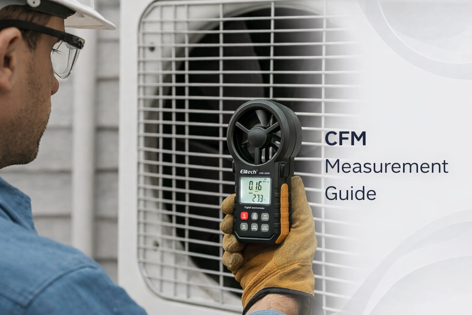
Step-by-Step: Measuring CFM with Anemometer
This is the part most people want. How do you actually measure CFM with an anemometer on a real HVAC job?
We’ll keep it simple and repeatable. The goal is not a perfect lab number. The goal is a number you can trust enough to make decisions and reduce call-backs.
Equipment needed
You need an anemometer that suits the job. There are different anemometer types, and they behave differently. A vane anemometer is often easier at grilles because it averages airflow across the vane face. A hot wire anemometer can be great for low flow or tight spots. A digital anemometer usually makes unit switching and averaging easier than older dial-style tools.
You also need a way to measure area. That can be as simple as a tape measure for grille dimensions, or a duct size reference if you’re measuring at a known duct opening.
If you’re setting up for regular airflow work, it’s worth starting with professional anemometers that are designed for field use and reporting. The right tool makes the method easier, not harder.
Measure the duct or grille area
Area is the size of the opening the air moves through. If you measure velocity but guess the area, your CFM result will be junk.
For a rectangular grille, measure height and width. For a round duct opening, measure diameter. On many jobs you are measuring at a grille face, so you use the grille’s effective opening area as your starting point.
Be careful here. A grille has blades and free area. The “face size” is not always the same as “free area”. If you need a high-confidence number for commissioning work, you may need to use the manufacturer’s free area data or a hood designed for airflow capture. But for fault-finding and consistency checks, face area with a consistent method is often enough to spot problems and improvements.
Take velocity readings
Now measure velocity with your anemometer. This is where technique matters.
Hold the meter square to the airflow. If you angle it, you can under-read or over-read depending on the sensor type. If the grille throws air sideways, you may need to position carefully or take more points to capture the average.
Don’t take one reading and walk away. HVAC airflow profiles are uneven. The centre may be fast, the corners may be slow, or the flow may “hug” one side because the duct take-off is biased.
A good field method is a simple grid. Move across the grille face and take multiple readings. Hold each reading steady long enough for the display to stabilise. Then average the readings.
Pro Tip
If your readings bounce, don’t chase the screen. Slow down, hold position, and average multiple points. Most “bad CFM numbers” are rushed technique, not a bad meter.
Calculate CFM (the simple field formula)
The classic field formula is simple.
CFM equals average velocity (in fpm) multiplied by area (in square feet).
If your meter reads in m/s, you can either convert to fpm or use metric flow units and convert at the end. The main thing is to keep units consistent all the way through the calculation.
What you do on site depends on your tool. Some digital anemometers can calculate flow if you enter the area. If yours does that, it can save time and reduce math errors. If it doesn’t, you can still do the calculation manually as long as you record your readings properly.
Multiple point measurement (why it matters)
Multiple points matter because the air is not evenly distributed. A single reading can be a “lucky” fast spot or a “bad” slow spot.
On a ducted system, this matters even more because duct runs, bends, and dampers create uneven velocity patterns. On a split system, it still matters because the discharge pattern can vary across the louvre and coil face.
When you average multiple points, you turn a messy real-world airflow profile into a usable number.
Record results properly
The best CFM reading in the world is worthless if you can’t explain how you got it later.
Record the location (which room, which grille), the measurement method (how many points, distance from grille), the unit (CFM, L/s, m³/h), and the conditions (filter clean or dirty, fan speed setting, doors open or closed).
This is the difference between “I think it’s better” and “Here’s the airflow change after the clean.”
Measurement Locations: Supply vs Return
Where you measure matters as much as how you measure.
Supply and return readings tell different stories. Supply helps you see what the system is delivering to rooms. Return helps you see whether the system can breathe. If the return is restricted, the supply numbers can be misleading because the fan is fighting a starving inlet.
It’s also common to measure at duct take-offs or access points, especially in commercial work or when grilles are hard to access. Each location has strengths and traps.
| Location | What it tells you | Best positioning technique | Common measurement errors |
|---|---|---|---|
| Supply grilles / diffusers | Room delivery, balance issues, “weak room” proof, before/after cleaning checks | Hold square to flow, use multiple points across the face, keep distance consistent | Measuring one fast spot, blocking flow with your body, angling the sensor, ignoring swirl |
| Return grilles | System breathing, restriction clues, filter and return path problems | Measure across the face, avoid pressing the meter into the grille, note filter condition | Reading too close to the grille, ignoring filter loading, not accounting for multiple return points |
| Duct take-offs / access openings | Duct flow confirmation, branch comparison, troubleshooting between fan and rooms | Use multiple points where possible, avoid measuring right at bends, document duct size clearly | Measuring in turbulence near elbows, assuming uniform flow, guessing duct area |
So, supply vs return. Supply tells you what people feel. Return tells you what the fan is fighting. You often need both to diagnose properly.
Here’s a common real job pattern. A customer says, “It’s not cooling like it used to.” Supply at the grille looks okay at first glance. But return velocity is low because the filter is clogged and the return path is restricted. The fan is starved, coil temperature drops, and performance suffers. If you only measure supply, you might miss the real cause.
Probe positioning is the make-or-break detail. Hold your tool square. Keep your distance consistent. Don’t block the airflow with your body. Take multiple points. Average them. Record what you did.
When you do that, supply vs return measurements become a simple diagnostic story instead of random numbers.
Australian Standards for Airflow Testing
In Australia, airflow testing often sits inside broader expectations about ventilation performance, maintenance, and documentation.
On residential jobs, the driver is usually comfort, noise, and performance. On commercial jobs, the driver can include indoor air quality, site requirements, maintenance contracts, and hygiene programs.
One commonly referenced Australian standard in this space is AS/NZS 3666. In practical terms, it’s tied to how air-handling systems are inspected and maintained to reduce hygiene risks. It’s not a “CFM chart” standard you use to set a bedroom airflow, but it does influence the idea that HVAC systems must be maintained, checked, and documented properly in many commercial settings.
That’s why airflow measurement matters in the real world. If a system is not performing as designed, you may see comfort complaints, condensation issues, and moisture problems that can become maintenance and hygiene headaches. Brisbane humidity is a classic example. Low airflow can make dehumidification feel weak even when the refrigeration circuit is fine, because the air is not moving across the coil in the way it should.
Design airflow versus actual airflow is another common issue. Many systems are designed with a target airflow, but real installs can drift away from that because of duct changes, filter choices, grille restrictions, and “quick fixes” over time. Measuring CFM with a consistent method helps you see the drift.
Documentation requirements vary by site. Some sites want clear records: what was measured, where it was measured, and what changed after maintenance. Even on smaller sites, good notes protect you. If you can show airflow improved after a clean, it builds trust and reduces arguments later.
If you’re building a broader compliance-ready kit, it helps to see how airflow testing fits alongside other checks like temperature, pressure, and electrical testing. This is covered well in Australian HVAC compliance tools, which frames airflow as one part of a sensible diagnostic workflow.
One practical reminder: safety and site rules matter when you’re measuring airflow. Ladders, ceiling spaces, and plant rooms can turn a “quick reading” into a risk if you rush it. Make sure your work method fits the site and the task, and keep your documentation habits aligned with workplace safety requirements.
Common CFM Problems in Australian Systems
If you start measuring CFM regularly, you’ll notice the same problem patterns again and again.
And the best part is this. Once you can spot the pattern, you can fix it faster, and you can explain it clearly to the customer or the site manager.
Low airflow causes (the usual suspects)
Low airflow is often not “mystery”. It’s restriction.
Dirty filters are the classic. A filter that looks “only a bit dusty” can still choke flow. Return grilles can mat up with lint. Evaporator coils can load with fine dust, especially where cleaning is skipped. Ducts can be crushed, kinked, or poorly supported. Dampers can stick or be left half closed.
On coastal Sydney jobs, corrosion can quietly reduce free area at grilles and dampers over time. On WA jobs, dry dust can build up in surprising places. In QLD, humidity makes the consequences worse because low airflow can turn into moisture complaints quickly.
High static pressure issues
High static pressure is a common reason CFM drops. The fan can be running, but it’s working too hard against restrictions, and the flow falls off.
Signs often show up as noisy return air, whistling grilles, or rooms that never balance properly. CFM readings help you prove it. If supply airflow is low across multiple outlets, and return airflow is also struggling, it’s a strong hint the system is choking somewhere.
Split system airflow issues
Split systems can be tricky because people assume “it’s just a fan and coil”. But airflow still matters a lot.
Common issues include blocked indoor filters, dirty coils, fan wheels loaded with dust, or incorrect fan mode settings. Even a slightly restricted indoor coil can change the feel of cooling and heating. Melbourne cold snaps often highlight this because heating mode needs the right air mass to move heat properly around the home.
When you measure, use a consistent method at the discharge. Don’t overpromise a perfect CFM number off a louvre, because the flow is directional and changes with vane angle. But do use readings to compare before and after cleaning, and to confirm whether one head is delivering far less than another in the same home.
Ducted system balancing
Ducted systems love imbalance. One short run can get “all the air”, while a long run starves.
CFM measurement helps you balance by evidence. Measure supply outlets, compare room to room, and adjust dampers with feedback. The goal is not chasing a perfect number. The goal is consistent comfort and a system that is not overworking.
If your readings look messy or inconsistent, don’t assume the tool is wrong. Slow down, repeat the same method, and change only one thing at a time. Try a consistent distance from the grille, take more points, and avoid measuring right at turbulence zones like sharp elbows and tight louvres. Most “weird airflow numbers” clean up with better positioning and a steadier averaging method.
Did You Know?
In Brisbane humidity, “low airflow” can look like “not cooling” because the system can’t manage moisture well. Fixing airflow can improve comfort even before you touch refrigerant.
Tropical climate considerations
Tropical and coastal climates make airflow faults louder.
When humidity is high, low airflow can create clammy comfort and longer run times. When salt air is present, grilles and outdoor exposures can degrade and add restriction. When temperatures swings, like in Melbourne, borderline airflow can flip from “fine” to “not coping” quickly.
That’s why consistent airflow testing is so useful. It catches the small drift before it becomes a big complaint.
Tools & Calculations: CFM Made Easy
This section is about making CFM practical. The goal is to reduce math mistakes and make airflow testing quick enough that you actually do it on busy days.
CFM calculator formulas (simple and safe)
The core idea stays the same. Flow equals velocity times area.
If you are using CFM, you need velocity in fpm and area in square feet. If you are using metric units, you can use m/s and square metres to get cubic metres per second, then convert to L/s or m³/h as needed.
If you prefer to keep everything metric for Australian reports, that’s fine. Just be consistent and label your results clearly. If the client asks for CFM, you can convert after you’ve recorded your base readings.
Duct sizing charts (use them carefully)
Duct charts can be helpful as a sanity check. They can tell you what an “expected” flow might look like for a given duct size and velocity range.
But don’t treat charts like truth. Real systems have bends, flex restrictions, coil pressure drop, filters, and grille losses. Use charts as a guide, then trust your measured results and the system behaviour.
Velocity to CFM conversion (avoid the common trap)
The common trap is mixing units. For example, using m/s with square feet, or using fpm with square metres. That will give you nonsense.
A simple habit helps. Write the unit next to the reading as you record it. If the meter is set to m/s, write m/s. If you switch to fpm, write fpm. That alone prevents most conversion mistakes.
Australian unit conversions (keep it simple)
On Australian jobs, you may have a mix of unit expectations. Some clients or docs use CFM. Many local reports prefer L/s or m³/h.
The best approach is to pick a primary reporting unit for the job and stick to it. Use conversions only when needed for communication or comparison.
Digital tool advantages (why they save time)
A digital anemometer is usually faster in the field because it can stabilise, average, and switch units easily. Many modern meters also help you record min/max values, which is useful when airflow pulses or the grille pattern is uneven.
If you’re building a kit that supports repeatable airflow work, it helps to browse professional anemometers with an eye for stability, unit options, and easy logging. You’re not chasing the fanciest tool. You’re chasing the tool you’ll actually use every week.
Tech Specs
Don’t buy on headline numbers alone. For CFM work, you want stable low-end readings, simple averaging, clear units, and a method you can repeat on the same grille every time.
Competitor comparison (when brand ecosystems matter)
Most of the time, the best airflow tool is the one that fits your workflow and gives repeatable readings. But sometimes, the tool ecosystem matters because of how you record and report.
This is where you’ll see techs compare brand-based systems. For example, some technicians like app-connected probe ecosystems for quick reporting and job records. Others prefer standalone meters with simple screens and fewer moving parts.
If you do a lot of logging and reporting, you may lean towards Bluetooth-style setups. They can help because you can set the probe, step back (so you don’t block the grille), and record a steadier value. For that workflow, wireless measurement tools can make CFM testing faster and more repeatable on busy days.
If your workflow is already built around a specific brand ecosystem for airflow measurement and reporting, you can compare options like Testo airflow meters alongside other common competitors used in Australia. The key is to keep it practical: does the tool help you measure, calculate, and record airflow without slowing you down?
Whatever brand you choose, keep the rules the same. Measure with a consistent method. Average multiple points. Record your location and conditions. Confirm anything that matters for compliance or commissioning using the correct job documentation and datasheets.
Professional Airflow Testing
At this point you’ve got the workflow.
You know what CFM is, how it links to velocity, and why you need both. You know how to measure area, take multiple velocity readings, and calculate a useful CFM number. You also know why supply and return measurements tell different stories, and how Australian job conditions can make airflow faults show up fast.
The next step is to turn this into a habit. The tradies who get the best outcomes don’t measure airflow once a year. They measure it whenever the symptoms point to it, and whenever they need to prove change after maintenance.
If you want to build confidence, keep your method consistent. Measure the same way each time on the same system. Record your numbers. Compare the next visit. That’s how you turn airflow testing into faster diagnostics and fewer repeat jobs.
When you’re ready to set up properly, start with quality airflow testing tools that match the jobs you do most often. If you’re unsure what suits your workflow, talk to our team to confirm compatibility and get a quote based on how you actually test in the field.
Airflow measurement is not about showing off. It’s about making decisions you can stand behind. When you can measure, explain, and document airflow properly, you reduce guesswork, you reduce call-backs, and you deliver a better result for the customer.
CFM Anemometer FAQs
What does CFM mean in HVAC?
CFM means cubic feet per minute. It’s a volume flow rate that tells you how much air is moving overall, not just how fast it feels at one point.
How do you calculate CFM using an anemometer?
Measure the opening area, take multiple velocity readings across the face, average them, then calculate flow using velocity multiplied by area. Keep your units consistent from start to finish to avoid bad results.
Why should you take multiple readings?
Grilles and ducts rarely have even airflow. Multiple points stop you getting tricked by one lucky fast spot or one dead zone, and give you a repeatable number you can use for diagnosis.
Should you measure supply or return?
Supply readings show what the space receives. Return readings show whether the system can breathe. For proper diagnosis, you often need both because a restricted return can reduce total airflow and distort what you see at supply points.
What causes “bad CFM numbers” most often?
The usual culprits are guessing area, mixing units, rushing a single reading, angling the meter, changing your distance from the grille, and blocking airflow with your body. A steady method fixes most of this.