Testoterm temperature labels are simple to apply correctly and easy to apply incorrectly. The difference matters because a label applied to a dirty surface, with air pockets under the sensing area, placed somewhere it cannot be inspected, or selected at the wrong threshold, produces either no useful information or misleading information. Either outcome wastes the label and leaves the equipment unmonitored. This guide walks through the complete application, reading, and logging workflow for Testoterm temperature labels — from pre-application checks through to replacement — so the labels you apply actually do the job they're designed to do. Unused labels should be stored below +25°C before use; for the range of Testoterm strip-style indicators and other formats available in Australia, confirm current stock and variants on the HVACShop product pages before ordering.
Reviewed by Rica Francia Macaspac | Published: May 2026 | Last reviewed: May 2026
Before You Apply a Testoterm Label
Three decisions need to be made correctly before touching the booklet: threshold selection, surface confirmation, and inspection planning. Getting these right before application is faster than replacing a label that was applied at the wrong threshold or in a location that cannot be inspected.
Threshold confirmation: Identify the component's rated normal operating surface temperature — from the equipment datasheet, nameplate, or manufacturer documentation. Select a threshold that sits clearly above the normal operating range but below the rated maximum. If the normal motor frame temperature is 55°C, a 65°C threshold provides only 10°C of margin — likely to activate on a warm day or during high-load operation without a fault being present. A 77°C or 82°C threshold provides more meaningful alert margin for that motor. Confirm the threshold variant you need is available before opening the booklet.
Surface confirmation: The surface must be accessible, flat or gently curved, free of ongoing lubricant contamination, and stationary. Rotating surfaces, heavily vibrating components, and surfaces subject to regular lubricant spray are not suitable for adhesive temperature labels. Confirm the surface will remain clean and accessible between application and the next inspection.
Inspection planning: Decide where on the surface the label will be placed so it can be read visually without removing covers, panels, or guards. A label hidden behind a panel that requires tool removal to access defeats the purpose of passive monitoring. Plan the placement location for maximum inspection accessibility before peeling the label.
Storage check: Unused Testoterm labels must be stored below +25°C in a clean, dry location. Check that booklets stored in the service vehicle have not been exposed to excessive heat — the interior of a closed vehicle in Queensland or NT summer can easily exceed safe storage limits, and pre-activated or adhesive-degraded labels from a hot vehicle will not produce reliable results. If in doubt about stored stock condition, use fresh booklets.
Step 1: Clean and Dry the Surface
Surface preparation is the step most commonly skipped and the step most likely to cause a label failure. The adhesive backing on a Testoterm label requires full contact with a clean, dry surface to achieve the thermal coupling needed for accurate response. Any layer of contamination between the label and the surface — oil film, dust, moisture, or residual cleaner — acts as a partial thermal insulator that slows or prevents the colour-change response.
Use an appropriate degreaser or solvent to remove oil and grease from the application area. On compressor housings and motor frames, even light oil contamination from normal operation can be present on accessible surfaces. Wipe the area clean, then allow the solvent to evaporate fully before applying the label. Applying over a solvent-damp surface risks adhesive contamination and poor bonding.

Remove any loose dust, paint flake, or surface debris before cleaning. On older equipment with flaking paint or corrosion, find a surface area that is clean and stable — avoid applying over loose or lifting surface material that will pull the label off as it continues to degrade.
After cleaning and drying, do not touch the application area with bare hands. Skin oils will re-contaminate the surface. If the surface area needs handling to position the label correctly, use a clean cloth or glove to handle adjacent areas without touching the cleaned application zone. For more detail on surface preparation and its effect on reading accuracy, our guide on how to read temperature strips accurately covers common preparation errors and their effect on results.
On compressor housings and motor frames in plant rooms, run a quick surface temperature check with a non-contact IR thermometer before applying labels. If the surface is already at 40°C or higher in ambient conditions — common on equipment in poorly ventilated rooms in Darwin or Brisbane in summer — a 65°C threshold label may be marginal. Document the ambient surface temperature at application time so you have context for any early activation you observe at the next inspection.
Step 2: Apply with Full Surface Contact
Peel the label carefully from the booklet, holding it by the edges and avoiding contact with the sensing face — the printed area that contains the threshold indicators. Fingerprint oils or skin contamination on the sensing area can interfere with the colour-change chemistry or obscure the visual result.

Position the label on the cleaned surface and press down firmly from the centre outward, using a finger or thumb to work any air pockets toward the edges. Air pockets under the label insulate the sensing area from the surface temperature. A label with even a small central air pocket may not respond accurately to surface temperature events — the air gap reduces thermal coupling between the surface and the sensing element.
On curved surfaces — motor frame cylindrical sections, pipe sections, compressor housings — the label edges will tend to lift as the label tries to conform to the curve. Press the edges down firmly after pressing the centre, and run a finger around the full perimeter of the label to ensure complete adhesion. If the label cannot conform to the curve without significant lifting, the surface curvature is too tight for that label format. Consider using the round Ø15 mm Testoterm Mini Indicators for tight spaces, which conform better to compact curved surfaces than rectangular formats.
After applying, give the label a final firm press across its full area. Do not apply on top of another label, over a previous label residue, or over a surface with uneven texture that prevents full contact.

Step 3: Read the Result
Reading a Testoterm label during inspection is straightforward, but requires knowing what you are looking for. An activated threshold point shows a permanent, clear colour change — typically a darkening or distinct colour shift — that contrasts visibly against the unactivated indicators. An unactivated point retains its original colour.
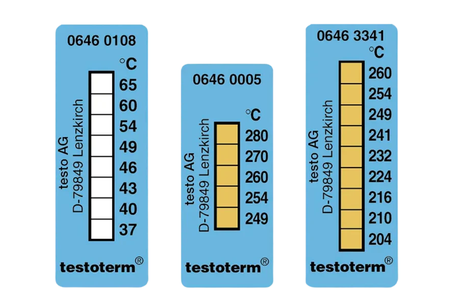
For Testoterm Measuring Points with a single threshold, the reading is binary: the indicator either shows the colour change (threshold was exceeded) or it does not (threshold was not reached). Record the result and move on.
For Multi-point formats like Mini Indicators, identify the highest threshold point that has activated. If the label shows activation at the 124°C point but not the 132°C point, the surface reached at least 124°C but did not reach 132°C during the monitoring period. Record the highest activated threshold as the minimum confirmed peak temperature.
The colour change is permanent and remains visible after the surface cools. A label inspected a month after a heat event will show the same activation pattern as one inspected immediately after. Do not discount an activated label because the surface is currently cool — the activation records a past event, not the current condition.
If a label appears partially activated — some indicator area changed, some did not — this may indicate an air pocket under the partially activated area, an inconsistent surface contact, or a heat event that approached but did not clearly exceed the threshold. Note the partial activation, photograph it, and consider whether the threshold or application method needs adjustment at the next cycle.
Step 4: Log and Replace
An activated Testoterm label has served its purpose the moment you observe the colour change. The next step is to capture the evidence before the label is replaced, and to record that evidence in a format that is useful for maintenance decision-making.

Photograph the activated label in place, alongside the asset tag, nameplate, or equipment ID. The photograph should show clearly which threshold was activated and which surface it was applied to. This is the primary evidence record — more reliable than a hand-written note, more durable than memory.
Record in your maintenance system: asset ID, location of the monitoring point, threshold of the activated label, date of inspection, date of original application, and any immediate observations about system condition at the time of inspection. If a fault condition is obvious — high head pressure, unusual noise, recent trip history — note the correlation.
Investigate the cause of the heat event before replacing the label if the activation is unexpected. A label that activates repeatedly at the same monitoring point after being replaced with the same threshold is telling you something systematic about that component's operating temperature. Investigate rather than simply replacing.
Replace the activated label with a fresh one after the investigation is complete and any corrective action has been taken. For transit and storage monitoring applications, the logging and replacement workflow for shipped equipment is covered in detail in our guide on irreversible temperature labels for shipping.
Mistakes to Avoid
Wrong threshold: Selecting a threshold too close to normal operating temperature produces labels that activate on every normal service cycle — providing no useful fault information and wasting consumables. Selecting a threshold too far above normal operating temperature means the label never activates, even during a genuine fault. Take the time to check the component's rated operating temperature before selecting a threshold.
Dirty surface: Applying to an oily, dusty, or damp surface is the most common cause of label failure. The consequence is a false negative — a surface that exceeds the threshold during an unattended period, but the label does not activate because poor surface contact prevented accurate thermal coupling. Clean the surface properly, every time.
Hidden placement: A label placed where it cannot be read without tool removal or panel disassembly may as well not exist for inspection purposes. Plan placement for visual accessibility before applying.
Using as a live thermometer: A Testoterm label does not show the current temperature. It shows the peak threshold reached during the monitoring period. Interpreting a non-activated label as "the surface is currently below threshold" is incorrect — it means the threshold was not reached during the monitoring period, which includes the current moment only incidentally. For live surface temperature, use a contact or non-contact thermometer.
Leaving stock in a hot vehicle: Interior vehicle temperatures in Australian summer can exceed +60°C in full sun. Testoterm stock stored in a closed vehicle during summer is at significant risk of adhesive degradation or pre-activation. Store booklets in a temperature-controlled location between jobs. Check stock condition before applying labels from booklets that have been through repeated hot-vehicle cycles. Storage and handling specifications are detailed in the product datasheet included with each Testoterm booklet.
The most reliable indicator monitoring programmes are built on consistency, not complexity. Using the same threshold, the same placement location, and the same inspection interval across all identical assets in a fleet makes results comparable and trends visible. Inconsistent threshold selection or irregular placement across similar assets produces data that cannot be meaningfully compared — reducing the programme's ability to identify which assets in the fleet are running hotter than the rest.