Temperature indicator stickers in HVAC work are passive surface-temperature monitoring tools — they record that a rated threshold was exceeded on a surface, between visits, without needing power, data connections, or attended measurement.
They are not diagnostic instruments. They do not replace a probe thermometer or a clamp meter. What they do is provide a physical, permanent record of a heat event that occurred on a surface while no technician was present.
In Australian HVAC/R maintenance, where service intervals can stretch weeks or months on large commercial portfolios, that passive evidence has genuine operational value. The Testo HVAC instruments range available in Australia includes the Testoterm indicator formats covered in this guide, alongside live measurement tools that complement them.
Reviewed by Rica Francia Macaspac | Published: May 2026 | Last reviewed: May 2026
Where Temperature Indicator Stickers Fit in HVAC Work
The clearest way to understand the role of temperature indicator stickers in HVAC is to distinguish between two types of temperature information: current readings and peak-event evidence.
A probe thermometer or non-contact IR gun gives you a current reading — what the surface is doing right now, at this moment, while you are standing in front of it.
A Testoterm temperature indicator sticker gives you peak-event evidence — whether a surface exceeded a rated threshold at any point during the monitoring period, including during the hours and days when no one was on site.
These are complementary, not competing, sources of information. A compressor that reads 72°C on a contact thermometer during a service visit may have reached 105°C at 2am on a hot Tuesday three weeks prior — a heat event that caused the high-pressure protection to trip, required a remote reset, and was logged as an unexplained fault.
A Testoterm label on the compressor shell would have captured that event permanently. Without the label, the next service visit finds a system that reads normal and produces no obvious explanation for the fault history.
Australian plant-room and rooftop conditions make this gap between attended service and unattended operation particularly significant. Equipment running in Darwin's heat, on a western-facing rooftop in Perth, or in a poorly ventilated plant room in Brisbane during summer faces ambient conditions that can push surface temperatures well above what they reach during a morning service call. Passive temperature indicators close that visibility gap without adding infrastructure, data connections, or ongoing power costs.
Compressor and Motor Monitoring
Compressors are the highest-value monitoring application for temperature indicator stickers in HVAC/R. Compressor failure is expensive — in parts, labour, downtime, and refrigerant — and heat events are one of the primary failure drivers. Monitoring compressor shell temperature, discharge line temperature, and motor winding temperature with irreversible labels gives maintenance teams evidence of heat events that correlates directly with fault history, warranty claims, and replacement decisions.

For compact compressor components where space is limited, compact heat labels for small HVAC components in the Ø15 mm Mini Indicator format fit surfaces where a larger strip would not make full contact.
Apply to the compressor shell at the motor end, to the discharge line within 150mm of the compressor outlet, or to accessible motor frame surfaces. Clean the surface thoroughly before application — oil film on a compressor housing is a common adhesion failure point that reduces thermal contact accuracy.
Electric motors on air handlers, condensing fans, and cooling tower units benefit from labels on the motor frame, particularly near the bearing housings and winding end. A motor approaching bearing failure produces localised heat at the bearing housing before any other symptom is evident. A Testoterm label at that location, set at an appropriate threshold above normal motor frame temperature, will activate before the bearing fails if a heat event occurs during an unattended period.
The threshold selection for compressor and motor monitoring should be based on the equipment's rated normal operating surface temperature, not an assumed value. Check the equipment datasheet or nameplate for rated maximum surface temperature. Select a Testoterm threshold that sits above the normal operating range but below the rated maximum — the alert margin should be meaningful, not marginal.
Switchboards and Electrical Components
Localised overheating in switchboards and electrical control panels is one of the more difficult diagnostic problems in commercial HVAC maintenance. The failure mode — a loose terminal connection, an overloaded relay, or a high-resistance busbar joint — produces heat at a specific point within the panel that may not be detectable during a visual inspection without thermal imaging equipment. Temperature indicator stickers provide a low-cost, always-on alternative to scheduled thermal imaging for panels where heating events are suspected but infrequent.
For switchboard applications, single-threshold Testoterm labels in the 14 x 14 mm Measuring Points format work well — they are small enough to fit near terminal blocks and relay clusters without obscuring wiring or interfering with components, and the binary threshold result is easy to read during a fast inspection.

Important safety context: applying temperature indicator stickers to electrical panels is a passive monitoring activity, not an electrical safety procedure. Labels monitor surface temperature only — they do not assess conductor temperature, insulation condition, load balance, or earthing integrity. Any corrective work identified through indicator activation must be performed by a licensed electrician. For general workplace safety context around hot electrical equipment, Safe Work Australia publishes guidance relevant to working around electrical hazards in commercial and industrial settings.
Place labels on the panel door inner surface near areas of concern, or on DIN rail sections near terminal clusters — not on live conductors or busbars directly. The label monitors the ambient surface temperature of the panel interior, which rises when a nearby component overheats. This is indicative monitoring, not a precise component measurement, but it is sufficient to flag panels that require closer investigation during the next attended inspection.
Pipework, Heat Exchangers and Cabinets
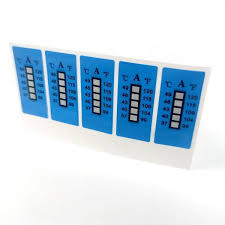
Broader flat surfaces — discharge and suction pipework, heat exchanger faces, refrigeration cabinet panels — suit the 50 x 18 mm strip format, which covers more surface area and is easier to read at a glance on a larger surface. Testoterm temperature strips for wider range checks span multiple temperature points across a broader indicator band, making them useful where you want to monitor a surface temperature range rather than a single threshold.

On pipework, apply strips to accessible straight sections away from bends, valves, or fittings where surface temperature may not be representative. On discharge lines, surface temperature reflects discharge gas temperature closely — a useful proxy for system operating conditions between service visits. On refrigeration cabinet panels, strips can confirm whether the cabinet exterior has exceeded a threshold that would indicate refrigeration failure or excessive ambient loading during an unattended period.
Heat exchanger monitoring with temperature strips is most useful on the liquid-line side of evaporators or the discharge side of condensers, where temperature events are most diagnostic. Apply to a representative flat section of the heat exchanger casing or associated pipework rather than directly to fin surfaces where adhesion may be inconsistent.
When to Use a Thermometer Instead
Temperature indicator stickers provide peak-event evidence. They do not provide current readings, trend data, or anything that can be used for live commissioning, active fault diagnosis, or real-time system performance assessment. For those applications, live measurement instruments are required.

| Situation | Use Temperature Indicator Sticker | Use Thermometer / Probe |
|---|---|---|
| Unattended monitoring between service visits | ✓ Passive, always-on, no power required | ✗ Requires attendance or data logging infrastructure |
| Warranty evidence — did this component exceed X°C? | ✓ Permanent irreversible record | ✗ Snapshot only; cannot prove past event |
| Live fault diagnosis — what is happening right now? | ✗ Does not show current temperature | ✓ Real-time reading |
| Commissioning and system performance check | ✗ Not appropriate for live data | ✓ Essential for commissioning documentation |
| Trend analysis over time | ✗ Binary event record only | ✓ Data logger or continuous monitoring instrument required |
| Recurring QA across a large asset fleet | ✓ Cost-effective, fast inspection, no infrastructure | ✗ Time-intensive if applied to every asset every visit |
For HVAC technicians, the most effective approach combines both: use HVAC thermometers and probes for active diagnosis during attended service visits, and use Testoterm indicators for passive peak-temperature monitoring between visits. The two tools answer different questions and work best in combination.
Implementation Checklist for Service Teams
1. Identify monitoring points on each asset type — compressor shell, motor frame, control cabinet door, discharge line, or other surfaces relevant to the equipment's failure modes and inspection priorities.
2. Select the appropriate threshold for each monitoring point based on the component's rated normal operating temperature and rated maximum. Document the threshold selection rationale so future team members understand why each threshold was chosen.
3. Clean surfaces with degreaser or solvent before application and allow to dry. Do not apply to oily, dusty, or wet surfaces.
4. Apply and photograph each label alongside a visible asset reference — nameplate, tag number, or equipment ID. The baseline photograph is the reference for comparison at the next inspection.
5. Record the threshold, location, asset ID, and application date in the maintenance management system or job sheet.
6. Inspect on each service visit — check for activation, photograph any activated labels before removing, log the event, investigate the cause, and replace with a fresh label after investigation.
7. Review threshold selections periodically. A label that activates on every normal service cycle is set at a threshold too close to normal operating temperature. A label that never activates after years of monitoring may be set too high to be useful. Both indicate a need to review the threshold selection. The industrial temperature strips guide covers advanced threshold selection and fleet monitoring programme design in detail.
In Australian commercial HVAC maintenance, temperature indicator stickers applied systematically across a service portfolio create a passive early-warning network that requires no infrastructure, no data connections, and no ongoing power. A technician arriving on site can inspect 30 monitoring points across a plant room in under 10 minutes, identifying any equipment that has experienced a heat event since the last visit — before running a single instrument check. That 10-minute scan can direct the rest of the service visit toward the equipment that actually needs attention.